您现在的位置是:首页 >技术教程 >基于目标级联法的微网群多主体分布式优化调度(已更新)网站首页技术教程
基于目标级联法的微网群多主体分布式优化调度(已更新)
简介基于目标级联法的微网群多主体分布式优化调度(已更新)
目录
一、主要内容
本文复现《基于目标级联法的微网群多主体分布式优化调度》文献的目标级联部分,
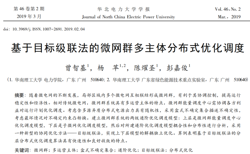
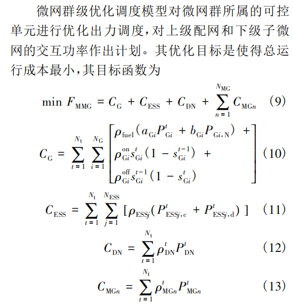
建立微网群系统的两级递阶优化调度模型: 上层是微网群能量调度中心优化调度模型,下层是子微网优化调度模型,然后对所建递阶优化调度模型耦合性和分布性进行分析,采用一种新型的协同优化方法———目标级联法,实现上下层模型的解耦独立优化,以3微网为算例进行验证,证明方法的可行性。
1.1 上层微网群模型
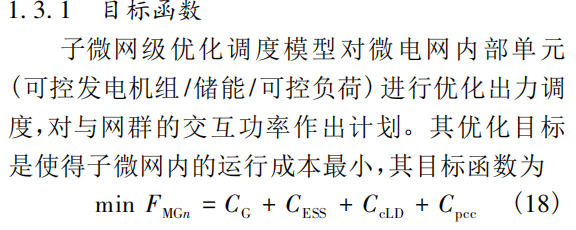
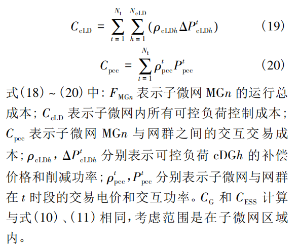
1.2 下层微网模型
二、部分程序
%程序开发时间:2023年1月26日

%欢迎关注微信公众号:电力程序

%----------------------------

%%目标级联协调优化

gPMG = zeros(3,24);%微网群与微网间联络功率

gPpcc1 = zeros(1,24);%微网1与微网群联络功率,下同

gPpcc2 =zeros(1,24);

gPpcc3 = zeros(1,24);

parameterATC;

figure(1);

errorSet = [];

for k=1:8

[y1(k),gPpcc1,x_P_g1,x_P_ch1,x_P_dis1,x_P_w1,x_P_v1,x_c_ld1,Load1]=lower1(pho,gPMG,v,w);%下层微网1

[y2(k),gPpcc2,x_P_ch2,x_P_dis2,x_P_w2,x_P_v2,x_c_ld2,Load2]=lower2(pho,gPMG,v,w);%下层微网2

[y3(k),gPpcc3,x_P_g3,x_P_ch3,x_P_dis3,x_P_w3,x_P_v3,x_c_ld3,Load3]=lower3(pho,gPMG,v,w);%下层微网3

[y4(k),gPMG]=upperthree(pho,v,w,gPpcc1,gPpcc2,gPpcc3);%上层微网群

%%----得到结果----

gPMG=value(gPMG);

gPpcc1=value(gPpcc1);

gPpcc2=value(gPpcc2);

gPpcc3=value(gPpcc3);

gPMGc(:,k)=gPMG(:,10);%10时刻微网群连接变量数据储存

gPpcc1c(k)=gPpcc1(10);%10时刻微网1连接变量数据储存

gPpcc2c(k)=gPpcc2(10);%10时刻微网2连接变量数据储存

gPpcc3c(k)=gPpcc3(10);%10时刻微网3连接变量数据储存

    postError = norm(gPMG-[gPpcc1;gPpcc2;gPpcc3])

    disp(sprintf('postError=%f',postError));

        errorSet = [errorSet postError];

        %画图

    figure(1),plot(errorSet),pause(0.1)

    xlabel('迭代次数');

    ylabel('误差值');

    v=v+2*w*w*postError;

    w=beta*w;

    yalmip('clear');

end

%最终迭代后结果图

figure;

ldz=max(x_c_ld1,0);

ldf=min(x_c_ld1,0);

wwz=max(gPpcc1,0);

wwf=min(gPpcc1,0);

yyf=[-x_P_ch1;ldf;wwf]';

bar(yyf,'stack');

hold on

yyz=[-x_P_dis1;x_P_g1;x_P_w1;x_P_v1;ldz;wwz]';

bar(yyz,'stack');

plot(Load1,'r','LineWidth',1.5)

xlabel('时间/h');

ylabel('功率/MW');

title('微网1功率');

sy=legend('储能充电','负荷响应','接受微网群电功率','储能放电','发电','风电','光伏','负荷响应','供给其他微网','微网1负荷');

sy.NumColumns = 3;

ylim([-6 14]);

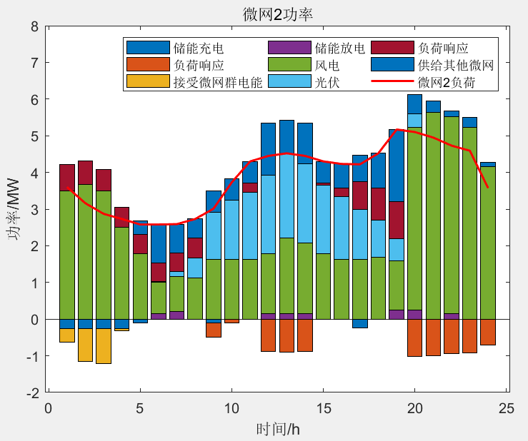
figure;

ldz=max(x_c_ld2,0);

ldf=min(x_c_ld2,0);

wwz=max(gPpcc2,0);

wwf=min(gPpcc2,0);

yyf=[-x_P_ch2;ldf;wwf]';

bar(yyf,'stack');

hold on

yyz=[-x_P_dis2;x_P_w2;x_P_v2;ldz;wwz]';

bar(yyz,'stack');

plot(Load2,'r','LineWidth',1.5)

xlabel('时间/h');

ylabel('功率/MW');

title('微网2功率');

sy=legend('储能充电','负荷响应','接受微网群电能','储能放电','风电','光伏','负荷响应','供给其他微网','微网2负荷');

sy.NumColumns = 3;

ylim([-2 8]);

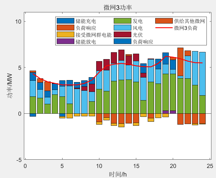
figure;

ldz=max(x_c_ld3,0);

ldf=min(x_c_ld3,0);

wwz=max(gPpcc3,0);

wwf=min(gPpcc3,0);

yyf=[-x_P_ch3;ldf;wwf]';

bar(yyf,'stack');

hold on

yyz=[-x_P_dis3;x_P_g3;x_P_w3;x_P_v3;ldz;wwz]';

bar(yyz,'stack');

plot(Load3,'r','LineWidth',1.5)

xlabel('时间/h');

ylabel('功率/MW');

title('微网3功率');

sy=legend('储能充电','负荷响应','接受微网群电能','储能放电','发电','风电','光伏','负荷响应','供给其他微网','微网3负荷');

sy.NumColumns = 3;

ylim([-5 11]);

figure;

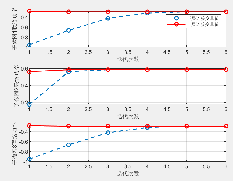
title_name = '微网群连接变量时段10趋同过程';

title(title_name);  %%关键

subplot(311)

plot(gPpcc1c,'o--','LineWidth',1.5)

hold on

plot(gPMGc(1,:),'r-o','LineWidth',1.5)

grid on

legend('下层连接变量值','上层连接变量值');

xlabel('迭代次数');

ylabel('子微网1联络功率');

subplot(312)

plot(gPpcc2c,'o--','LineWidth',1.5)

hold on

plot(gPMGc(2,:),'r-o','LineWidth',1.5)

grid on

xlabel('迭代次数');

ylabel('子微网2联络功率');

subplot(313)

plot(gPpcc3c,'o--','LineWidth',1.5)

hold on

plot(gPMGc(3,:),'r-o','LineWidth',1.5)

grid on

xlabel('迭代次数');

ylabel('子微网3联络功率');
三、实现效果
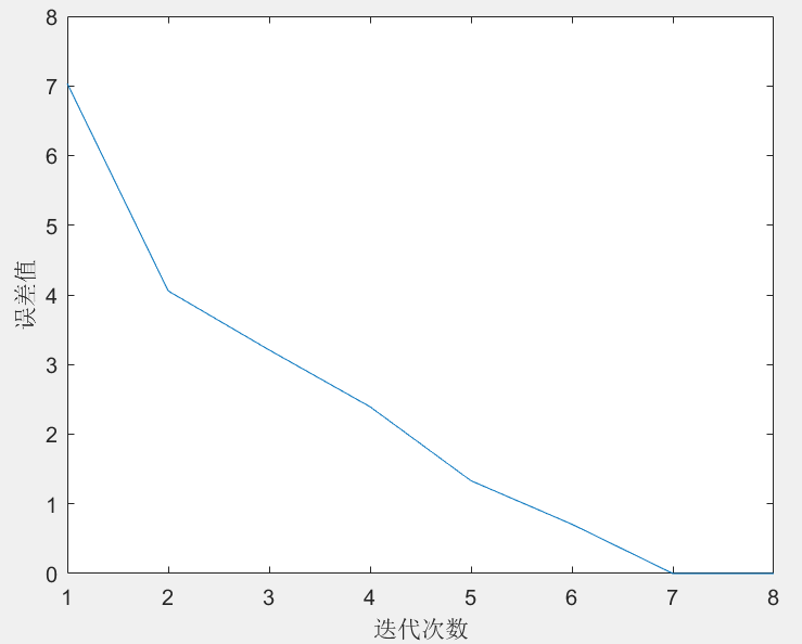
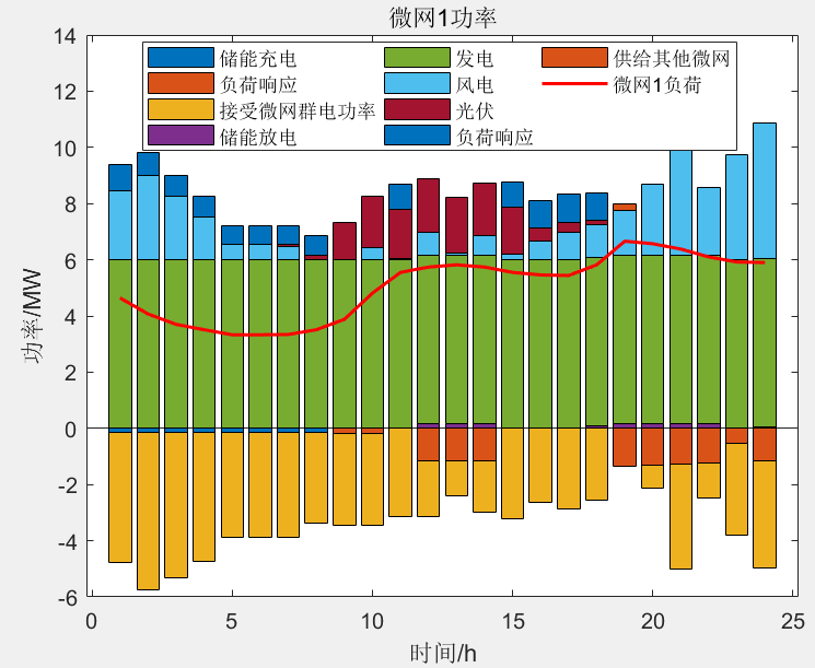
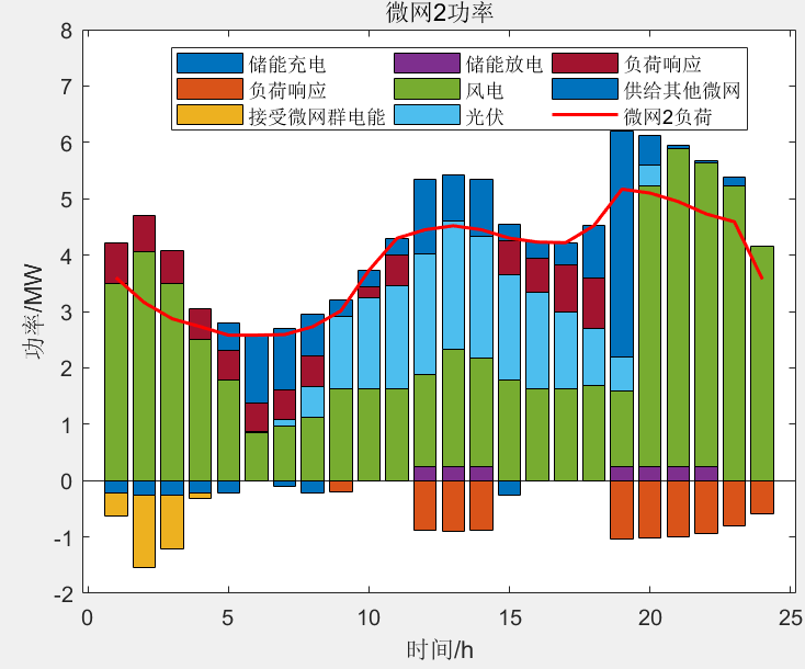
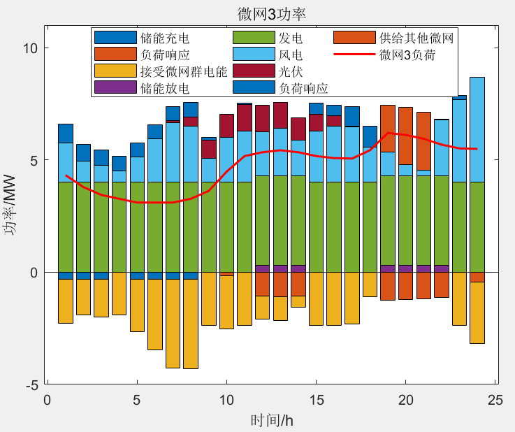
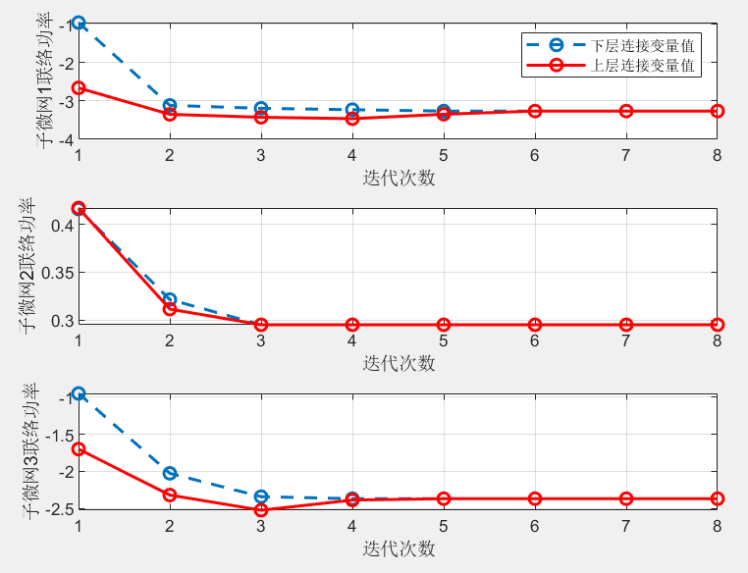
以上是按照文献编写的程序,存在一个问题:联络线功率之和不为零,一般而言,微网群中供应功率和吸收功率应该是守恒的,因此,对该部分进行了完善,实现效果如下:

四、下载链接
风语者!平时喜欢研究各种技术,目前在从事后端开发工作,热爱生活、热爱工作。


 U8W/U8W-Mini使用与常见问题解决
 QT多线程的5种用法,通过使用线程解决UI主界面的耗时操作代码,防止界面卡死。...
 stm32使用HAL库配置串口中断收发数据(保姆级教程)
 分享几个国内免费的ChatGPT镜像网址(亲测有效)
 Allegro16.6差分等长设置及走线总结