您现在的位置是:首页 >技术教程 >QT With OpenGL(SSAO)(Screen-Space Ambient Occlusion)网站首页技术教程
QT With OpenGL(SSAO)(Screen-Space Ambient Occlusion)
文章目录
在G_Buffer中加入深度信息
- 将深度转化为线性
float LinearizeDepth(float depth)
{
    float z = depth * 2.0 - 1.0; // 回到NDC
    return (2.0 * NEAR * FAR) / (FAR + NEAR - z * (FAR - NEAR));
}
- 将深度记录在position的alpha值中。
gPositionDepth.a = LinearizeDepth(gl_FragCoord.z);
注:深度的范围不能局限在【0,1】,所以需要设置纹理数据类型为GL_RGBA16F。纹理封装方法设置为GL_CLAMP_TO_EDGE
使用深度信息得到环境遮蔽的结果
首先我们需要在该片段(像素)的法线半球方向上采样
1. 新建SSAO帧缓存类
#include <QOpenGLFunctions>
#include <QOpenGLFramebufferObject>
#include <QOpenGLShaderProgram>

class SSAO : public QOpenGLFunctions
{
public:
    QOpenGLFramebufferObject* SSAOFBO;
    QOpenGLShaderProgram *SSAOShader;
    QVector<QVector3D> SSAOKernel;

public:
    SSAO(int w,int h);
    void generateKernel();
    void setUniform();
    ~SSAO();
};
2.生成法向半球核心
void SSAO::generateKernel()
{
    for(int i=0;i<64;++i){
        QVector3D sample(random_double(-1,1),random_double(-1,1),random_double(0,1));
        sample.normalize();//生成一个半球面的随机向量
        sample *= random_double(0,1);//将随机向量均匀分布在半球体内
        double scale = double(i)/64.0;
        scale = 0.1 + scale*scale*(0.9);//将随机向量再次缩放,使绝大多数采样点接近原点
        sample *= scale;
        SSAOKernel.push_back(sample);
    }
}
3. 生成随机核心转动纹理
为什么要生成随机核心转动
- 如果对每一个像素都随机生成64个采样向量,那么性能将会受到很大影响。
- 如果对于每一个像素都使用同一个64随机采样向量,效果不好???
- 如果对于每一个像素,都将改64随机采样向量做一次旋转,则会得到更为随机的采样
因此引入随机核心转动
如果我们对场景中每一个片段创建一个随机旋转向量,这会很快将内存耗尽。
所以,更好的方法是创建一个小的随机旋转向量纹理平铺在屏幕上。
创建一个小的随机旋转向量纹理
    for(int i=0;i<16;++i){
        QVector3D noise(random_double(-1,1),random_double(-1,1),0.0);
        SSAONoise.push_back(noise);
    }
使用OpenGL函数绑定到纹理
{
    GLuint noiseTexture;
    glGenTextures(1, &noiseTexture);
    glBindTexture(GL_TEXTURE_2D, noiseTexture);
    glTexImage2D(GL_TEXTURE_2D, 0, GL_RGB16F, 4, 4, 0, GL_RGB, GL_FLOAT, &SSAONoise[0]);
    glTexParameteri(GL_TEXTURE_2D, GL_TEXTURE_MIN_FILTER, GL_NEAREST);
    glTexParameteri(GL_TEXTURE_2D, GL_TEXTURE_MAG_FILTER, GL_NEAREST);
    glTexParameteri(GL_TEXTURE_2D, GL_TEXTURE_WRAP_S, GL_REPEAT);
    glTexParameteri(GL_TEXTURE_2D, GL_TEXTURE_WRAP_T, GL_REPEAT);
    glActiveTexture(GL_TEXTURE0);
    glBindTexture(GL_TEXTURE_2D,noiseTexture);
}
使用QT::QOpenGLTexture,绑定到QOpenGLTexture类。
{
    texture.setSize(4,4,1);
    texture.setFormat(QOpenGLTexture::RGBFormat);
    texture.allocateStorage(QOpenGLTexture::RGB,QOpenGLTexture::Float32);
    texture.setData(0,QOpenGLTexture::RGB,QOpenGLTexture::Float32,(void*)SSAONoise.data());
    texture.setMinMagFilters(QOpenGLTexture::Nearest,QOpenGLTexture::Nearest);
    texture.setWrapMode(QOpenGLTexture::Repeat);
    glActiveTexture(GL_TEXTURE0);
    texture.bind();
}
效果展示
//test
debugShader = new QOpenGLShaderProgram();
debugShader->addShaderFromSourceFile(QOpenGLShader::Vertex,":/map_depth.vert");
debugShader->addShaderFromSourceFile(QOpenGLShader::Fragment,":/map_depth.frag");
debugShader->link();

debugShader->bind();//shader
debugShader->setUniformValue("depthMap",0);
renderQuad();
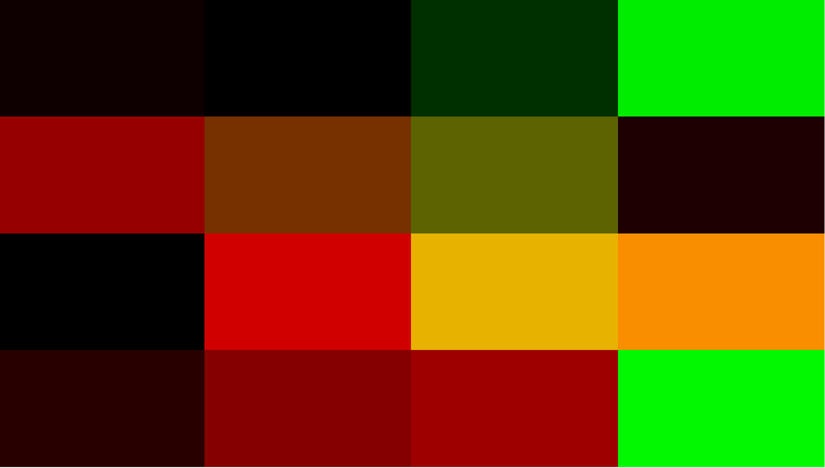
纹理成功生成。
4.使用G_Buffer渲染SSAO纹理
传入参数
- gPositionDepth (观察空间(View Space))位置深度信息
- gNormal 法线信息
- noiseTexture 随机法向半球
- samples[64]; 64个采样向量
注意: SSAO需要的位置信息是视口(View) 角度下看到的物体的视口坐标信息和深度,这与之前做延迟渲染(Deferred Shader) 不同,延迟渲染需要的信息为视口角度下物体的世界坐标信息。
因此若要统一G_Buffer,需要将G_Buffer提供的位置深度信息统一为视口坐标下的位置深度信息。在延迟渲染中,将
视口矩阵
∗
光源信息
视口矩阵*光源信息
视口矩阵∗光源信息 ,使整个光照渲染都在视口坐标系下进行。
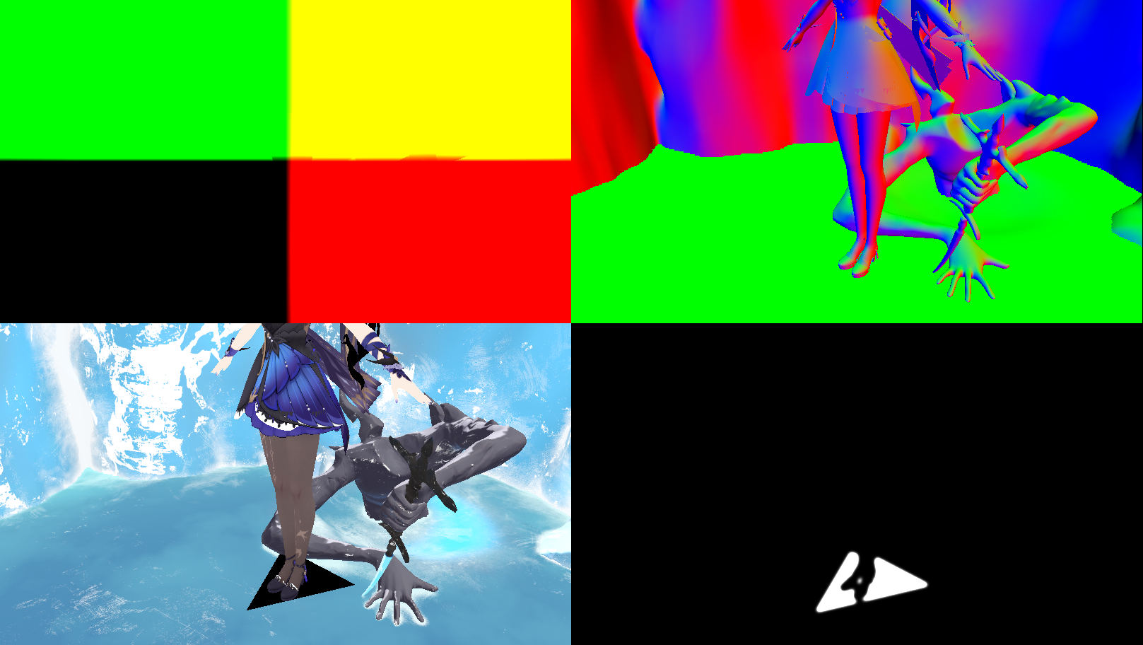
gPosition不再是世界坐标,而是视口坐标(第一张图)
着色器
1. 获取当前像素在纹理中的信息
width,height为当前屏幕的大小
const vec2 noiseScale = vec2(width/4.0f, height/4.0f);
    // Get input for SSAO algorithm
    vec3 fragPos = texture(gPositionDepth, TexCoords).xyz;
    vec3 normal = texture(gNormal, TexCoords).rgb;
    vec3 randomVec = texture(texNoise, TexCoords * noiseScale).xyz;
若渲染(0,0)像素点,随机转动核心纹理为(0,0)点
若渲染(
1
/
w
i
d
t
h
1/width
1/width,
1
/
h
e
i
g
h
t
1/height
1/height)像素点,随机转动核心纹理为(
1
/
4
1/4
1/4,
1
/
4
1/4
1/4)点
即每4X4个像素使用一组随机转动核心纹理。
2.计算TBN矩阵
已知Normal向量,获得了一个随机向量randomVec
(
x
,
y
,
0
)
(x,y,0)
(x,y,0),求TBN。
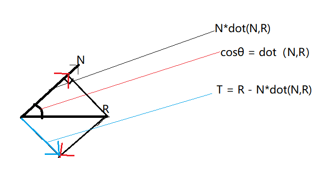
    // Create TBN change-of-basis matrix: from tangent-space to view-space
    vec3 tangent = normalize(randomVec - normal * dot(randomVec, normal));
    vec3 bitangent = cross(normal, tangent);
    mat3 TBN = mat3(tangent, bitangent, normal);
关于切线空间的内容可参考
3. 遍历采样点
将样本从切线空间变换到观察空间
float occlusion = 0.0;
for(int i = 0; i < kernelSize; ++i)
{
    // 获取样本位置
    vec3 sample = TBN * samples[i]; // 切线->观察空间
    sample = fragPos + sample * radius;

    [...]
}
变换sample从观察空间到屏幕空间
    vec4 offset = vec4(Tsample, 1.0);
    offset = projection * offset; // 观察->裁剪空间
    offset.xyz /= offset.w; // 透视划分
    offset.xyz = offset.xyz * 0.5 + 0.5;// 变换到0.0 - 1.0的值域
获取采样点像素的屏幕深度值
float sampleDepth = -texture(gPositionDepth, offset.xy).w;
引入范围测试从而保证我们只当被测深度值在取样半径内时影响遮蔽因子
fragPos.z是渲染点深度
sampleDepth是采样点的像素深度
smoothstep的意义可参照Shader实验室: smoothstep函数
float rangeCheck = smoothstep(0.0, 1.0, radius / abs(fragPos.z - sampleDepth ));
occlusion += (sampleDepth >= Tsample.z ? 1.0 : 0.0) * rangeCheck;
如果
∣
f
r
a
g
P
o
s
.
z
−
s
a
m
p
l
e
D
e
p
t
h
∣
<
r
a
d
i
u
s
|fragPos.z - sampleDepth|<radius
∣fragPos.z−sampleDepth∣<radius,则rangeCheck=1
如果
∣
f
r
a
g
P
o
s
.
z
−
s
a
m
p
l
e
D
e
p
t
h
∣
>
r
a
d
i
u
s
|fragPos.z - sampleDepth|>radius
∣fragPos.z−sampleDepth∣>radius,则rangeCheck
∈
(
0
,
1
)
in(0,1)
∈(0,1)
当
∣
f
r
a
g
P
o
s
.
z
−
s
a
m
p
l
e
D
e
p
t
h
∣
>
r
a
d
i
u
s
|fragPos.z - sampleDepth|>radius
∣fragPos.z−sampleDepth∣>radius并不直接移除遮蔽贡献是因为,这样会在范围检测边缘看到很明显的边界。因此使用距离远近改变贡献度。
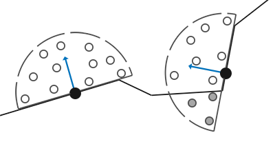
当采样点像素深度(物体边缘)大于等于检测点深度(空心圈),说明该点未遮蔽了渲染点的环境光照,Occlusion遮蔽值增加。
将遮蔽贡献根据核心的大小标准化
occlusion / kernelSize 得到未遮蔽系数,再用1减去,得到遮蔽系数。
occlusion = 1.0 - (occlusion / kernelSize);
FragColor = occlusion;
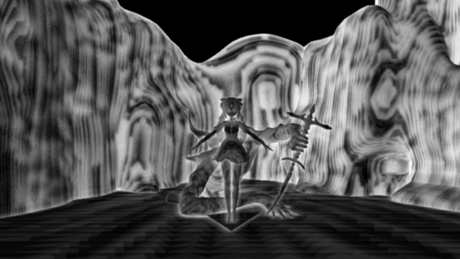
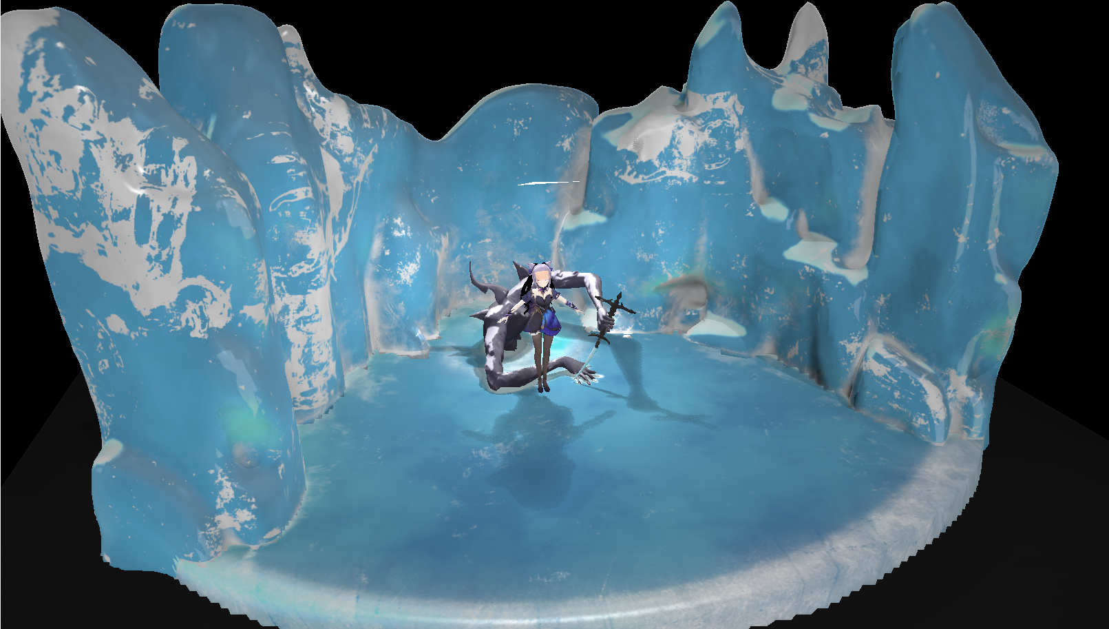
SSAO输出测试



 QT多线程的5种用法,通过使用线程解决UI主界面的耗时操作代码,防止界面卡死。...
 U8W/U8W-Mini使用与常见问题解决
 stm32使用HAL库配置串口中断收发数据(保姆级教程)
 分享几个国内免费的ChatGPT镜像网址(亲测有效)
 Allegro16.6差分等长设置及走线总结