您现在的位置是:首页 >学无止境 >spi 应用层读值为0问题网站首页学无止境
spi 应用层读值为0问题
简介spi 应用层读值为0问题
昨天调SPI遇到读值为0x00,经排查是读写方向的问题。
#include <stdint.h>
#include <stdio.h>
#include <stdlib.h>
#include <string.h>
#include <fcntl.h>
#include <unistd.h>
#include <getopt.h>
#include <sys/ioctl.h>
#include <linux/spi/spidev.h>
#include <linux/types.h>

#define D_SPI_READ_OP			( 1 << 7 )

static const char *device = "/dev/spidev0.0";
static int s_fd = -1;
static uint8_t mode = SPI_MODE_0;
static uint8_t bits = 8;
static uint32_t speed = 24000000;

static void pabort(const char *s)
{
	perror(s);
	abort();
}

void spi_init_test()
{
    int ret = 0;

    s_fd = open(device, O_RDWR);
    if (s_fd < 0)
        pabort("can't open device");

    printf("open device sucucess %s
", device);
   /*
    * spi mode
     */
    ret = ioctl(s_fd, SPI_IOC_WR_MODE, &mode);
    if (ret == -1)
        pabort("can't set spi mode");

    ret = ioctl(s_fd, SPI_IOC_RD_MODE, &mode);
    if (ret == -1)
        pabort("can't get spi mode");

    /*
     * bits per word
     */
    ret = ioctl(s_fd, SPI_IOC_WR_BITS_PER_WORD, &bits);
    if (ret == -1)
        pabort("can't set bits per word");

    ret = ioctl(s_fd, SPI_IOC_RD_BITS_PER_WORD, &bits);
    if (ret == -1)
        pabort("can't get bits per word");

    /*
     * max speed hz
     */
    ret = ioctl(s_fd, SPI_IOC_WR_MAX_SPEED_HZ, &speed);
    if (ret == -1)
        pabort("can't set max speed hz");

    ret = ioctl(s_fd, SPI_IOC_RD_MAX_SPEED_HZ, &speed);
    if (ret == -1)
        pabort("can't get max speed hz");

    printf("spi mode: %d
", mode);
    printf("bits per word: %d
", bits);
    printf("max speed: %d Hz (%d KHz)
", speed, speed/1000);
}

int SPI_Transfer(const uint8_t * tx_buf, uint8_t * rx_buf, int len)
{
	int ret;
	int i;

	struct spi_ioc_transfer tr ={
		.tx_buf = (unsigned long) tx_buf,
		.rx_buf = (unsigned long) rx_buf,
		.len =len,
		.delay_usecs = 0,
	};

	ret = ioctl(s_fd, SPI_IOC_MESSAGE(1), &tr);
	if (ret < 1)
		printf("can't send spi message");
	else
	{
		printf("SPI Send [Len:%d]
", len);
		printf("SPI Receive [len:%d]:", len);

		for (i = 0; i < len; i++)
		{
			printf("0x%02x ", rx_buf[i]);	// rx_buf[0]为0x00, rx_buf[1]是有效数据,还需找找原因。
		}
		printf("
");
	}

	return ret;
}

int main()
{
	uint8_t r_buf[16] = {0};
	//uint8_t w_buf[12] = {0x1f, 0x20, 0x21, 0x22, 0x23, 0x24, 0x25, 0x26, 0x27, 0x28, 0x29, 0x2a};
	uint8_t w_buf[1] = {0x75 | D_SPI_READ_OP};
	uint8_t ag_buf[1] = {0x1f | D_SPI_READ_OP};
	spi_init_test();
	while (1) {
		SPI_Transfer(w_buf, r_buf, 2);
		SPI_Transfer(ag_buf, r_buf, 12);
		usleep(1000*1000);
	}

	return 0;
}
/*
* SPI操作功能 (IMU ICM42686 手册上[9.6 SPI INTERFACE ]描述)
*/
1.数据首先传递MSB,最后传递LSB
2.数据在SCLK的上升沿被锁存
3.数据应在SCLK的下降沿上转换
4.SCLK的最大频率为24 MHz
5.SPI读取和写入操作在16个或更多时钟周期(两个或更多字节)中完成。
第一个字节包含SPI地址,后面的字节包含SPI数据。
第一个字节的第一位包含读/写位,并指示读 (1) 或写 (0) 操作。
以下7位包含寄存器地址。在多字节读/写的情况下,数据为两个或更多字节:
SPI Address format
MSB LSB
R/W A6 A5 A4 A3 A2 A1 A0
SPI Data format
MSG LSB
D7 D6 D5 D4 D3 D2 D1 D0
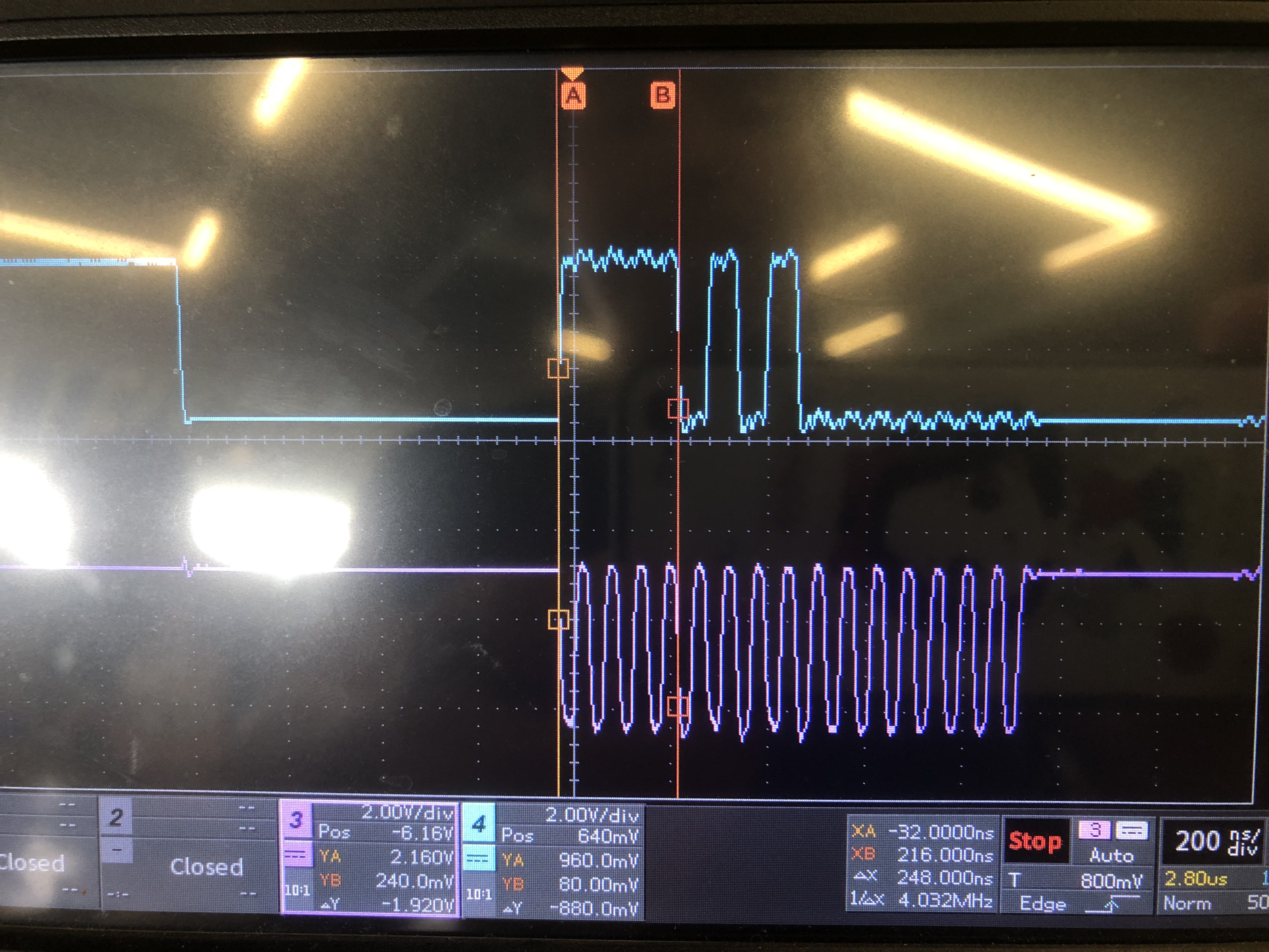
图:spi mode 3 波形图 ,寄存器0x75加上读标志1后为0xf5。

图:spi mode 0 波形图 ,寄存器0x75加上读标志1后为0xf5。

风语者!平时喜欢研究各种技术,目前在从事后端开发工作,热爱生活、热爱工作。


 U8W/U8W-Mini使用与常见问题解决
 QT多线程的5种用法,通过使用线程解决UI主界面的耗时操作代码,防止界面卡死。...
 stm32使用HAL库配置串口中断收发数据(保姆级教程)
 分享几个国内免费的ChatGPT镜像网址(亲测有效)
 Allegro16.6差分等长设置及走线总结