您现在的位置是:首页 >技术教程 >通信调制信号及时频图数据集制作(MATLAB)网站首页技术教程
通信调制信号及时频图数据集制作(MATLAB)
一、说明
实现平台:MATLAB2022b
二、调制信号产生及保存
首先产生调制信号,包括八种数字调制类型和三种模拟调制类型:
-
二相相移键控 (BPSK)
-
四相相移键控 (QPSK)
-
八相相移键控 (8-PSK)
-
十六相正交幅值调制 (16-QAM)
-
六十四相正交幅值调制 (64-QAM)
-
四相脉冲幅值调制 (PAM4)
-
高斯频移键控 (GFSK)
-
连续相位频移键控 (CPFSK)
-
广播 FM (B-FM)
-
双边带幅值调制 (DSB-AM)
-
单边带幅值调制 (SSB-AM)
产生的调制信号每种调制类型每种SNR等级生成 1000个帧,每帧的长度为 1024 个样本,采样率为 200 kHz。对于数字调制类型,八个采样表示一个符号,其中数字和模拟调制类型的中心频率分别为 902 MHz 和 100 MHz。
所有信号均通过信道减损采样,包括:
-
AWGN
-
莱斯多径衰落
-
时钟偏移,导致中心频率偏移和采样时间漂移
AWGN
通道增加 SNR 为 30 dB 的 AWGN。使用 awgn (Communications Toolbox) 函数实现通道。
莱斯多径
通道使用Communications Toolbox中的 comm.RicianChannel 实现,通过莱斯多径衰落通道传递信号。假设延迟分布为 [0 1.8 3.4] 个样本,对应的平均路径增益为 [0 -2 -10] dB。K 因子为 4,最大多普勒频移为 4 Hz,等效于 902 MHz 的步行速度。使用以下设置实现通道。
时钟偏移
时钟偏移是发射机和接收机的内部时钟源不准确造成的。时钟偏移导致中心频率(用于将信号下变频至基带)和数模转换器采样率不同于理想值。通道仿真器使用时钟偏移因子 C,表示为 ,其中 Δclock 是时钟偏移。对于每个帧,通道基于 [−maxΔclock maxΔclock] 范围内一组均匀分布的值生成一个随机 Δclock 值,其中 maxΔclock 是最大时钟偏移。时钟偏移以百万分率 (ppm) 为单位测量。对于本示例,假设最大时钟偏移为 5 ppm。
频率偏移
基于时钟偏移因子 C 和中心频率,对每帧进行频率偏移。使用 Communications Toolbox中的 comm.PhaseFrequencyOffset实现通道。
采样率偏移
基于时钟偏移因子 C,对每帧进行采样率偏移。使用 interp1 函数实现通道,以 C×fs 的新速率对帧进行重新采样。
最后为每种调制类型生成通道减损的帧并将这些帧及其对应标签存储在 MAT 文件中。
实现代码:
% generate the wave

modulationTypes = categorical(["BPSK", "QPSK", "8PSK", ...
  "16QAM", "64QAM", "PAM4", "GFSK", "CPFSK", ...
  "B-FM", "DSB-AM", "SSB-AM"]);
%产生数据-8:30dB

SNR  = -8:2:30;                             %SNR范围
maxOffset = 5;

Generate_data = true;
if Generate_data == true
  numFramesPerModType = 1000;               %每个信号产生帧数
else
  numFramesPerModType = 500;
end

sps = 8;                % Samples per symbol
spf = 1024;             % Samples per frame
symbolsPerFrame = spf / sps;
fs = 200e3;             % Sample rate
fc = [902e6 100e6];     % Center frequencies

% find the clock offset
maxDeltaOff = 5;
deltaOff = (rand()*2*maxDeltaOff) - maxDeltaOff;
C = 1 + (deltaOff/1e6);


rng(1235)
tic

numModulationTypes = length(modulationTypes);          %numModulationTypes = 11
numSNR_level = length(SNR);                            %numSNR_levle = 14

transDelay = 50;
dataDirectory = fullfile(tempdir,"ModClassDataFiles"); %默认保存路径
disp("Data file directory is " + dataDirectory)
fileNameRoot = "frame";

% 检查数据文件是否存在
dataFilesExist = false;
if exist(dataDirectory,'dir')
  files = dir(fullfile(dataDirectory,sprintf("%s*",fileNameRoot)));
  if length(files) == numModulationTypes*numFramesPerModType
    dataFilesExist = true;
  end
end

if ~dataFilesExist
  disp("Generating data and saving in data files...")
  [success,msg,msgID] = mkdir(dataDirectory);
  if ~success
    error(msgID,msg)
  end

  for snrLevel = 1:numSNR_level                           %第一个循环,SNR级别

      % 信道设计
      channel = helperModClassTestChannel('SampleRate', fs, 'SNR', SNR(snrLevel), ...
      'PathDelays', [0 1.8 3.4] / fs, ...
      'AveragePathGains', [0 -2 -10], ...
      'KFactor', 4, ...
      'MaximumDopplerShift', 4, ...
      'MaximumClockOffset', 5, ...
      'CenterFrequency', 902e6);
      channelInfo = info(channel);

      for modType = 1:numModulationTypes                 %第二个循环,调制信号类型
        fprintf('%s - Generating %s frames %d SNR(dB)
', ...
      datestr(toc/86400,'HH:MM:SS'), modulationTypes(modType),SNR(snrLevel))

      label = modulationTypes(modType);
      label_snr = SNR(snrLevel);
      numSymbols = (numFramesPerModType / sps);
      dataSrc = helperModClassGetSource(modulationTypes(modType), sps, 2*spf, fs);
      modulator = helperModClassGetModulator(modulationTypes(modType), sps, fs);
      if contains(char(modulationTypes(modType)), {'B-FM','DSB-AM','SSB-AM'})
        % Analog modulation types use a center frequency of 100 MHz
        channel.CenterFrequency = 100e6;
      else
        % Digital modulation types use a center frequency of 902 MHz
        channel.CenterFrequency = 902e6;
      end

      for p=1:numFramesPerModType                      %第三个循环,调制信号帧数
        % Generate random data
        x = dataSrc();

        % Modulate
        y = modulator(x);

        % Pass through independent channels
        rxSamples = channel(y);

        % Remove transients from the beginning, trim to size, and normalize
        frame = helperModClassFrameGenerator(rxSamples, spf, spf, transDelay, sps);

        % Save data file 保存文件名为 frame+调制信号类型+信噪比级别+序号
        fileName = fullfile(dataDirectory,...
          sprintf("%s%s%ddB%03d",fileNameRoot,modulationTypes(modType),SNR(snrLevel),p));
        save(fileName,"frame","label","label_snr")
      end
      end
  end
else
  disp("Data files exist. Skip data generation.")
end
产生结果:


三、时频图转换及保存
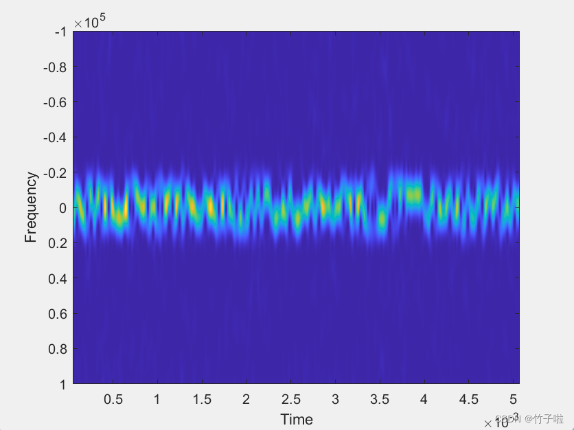
将信号转换为时频图主要使用pspectrum函数:
[p,f,t]=pspectrum(frame,fs,'spectrogram','TimeResolution',10e-5,...
'OverlapPercent',99,'Leakage',0.85);
其中frame是在上一步保存的调制信号,fs为采样率,‘spectrogram’表示选择计算短时功率谱估计,‘TimeResolution’的数值代表画出的时频图中信号的宽度,'OverlapPercent'表示信号重叠的程度,'Leakage'代表频谱泄露,主要控制Kaiser窗中旁瓣相对于主瓣的衰减。
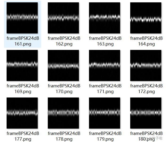
程序设计步骤为先读取信号数据,接着进行时频图转换操作,将得到的时频图尺寸裁剪并复制通道(该操作主要适用于后续深度学习中模型输入使用),最后保存至对应调制信号的文件夹中,保存的文件名和调制信号数据的文件名相同,保存的图像为灰度图像。
根据SNR实际需求,设计两种程序,第一种为混合信噪比数据集,即不区分SNR等级,同种信号类型包含所有的SNR等级;第二种是区分信噪比数据集,即在每种信噪比等级下包含所有的信号类型。本文仅展示混合信噪比数据集实现。
混合信噪比具体实现代码:
%混和信噪比产生时频图并保存

fs = 200e3;                                               %采样率

dataSetDir = '...dataset';

fileList = dir(fullfile(dataSetDir, '*.mat'));
for i = 1:length(fileList)
    load(fullfile(dataSetDir, fileList(i).name));

    % 时频转换操作
    [p,f,t]=pspectrum(frame,fs,'spectrogram','TimeResolution',10e-5,'OverlapPercent',99,'Leakage',0.85);
%     imagesc(t,f,abs(p));                               %展示时频图
%     xlabel('Time');
%     ylabel('Frequency');
    fileName = fileList(i).name;
    fileName = strrep(fileName, '.mat', '');
    Image1 = imresize(abs(p),[224 224]);                 %裁剪尺寸为224*224
    Image3 = cat(3,Image1,Image1,Image1);                %复制三个通道,保存为224*224*3格式
    if contains(fileName, '8PSK')                        %对应信号保存至对应文件夹(需要提前创建)
        imwrite(Image3,fullfile('...8PSK',sprintf('%s.png',fileName)));
    elseif contains(fileName, 'CPFSK')
        imwrite(Image3,fullfile('...CPFSK',sprintf('%s.png',fileName)));
    elseif contains(fileName, 'QPSK')
        imwrite(Image3,fullfile('...QPSK',sprintf('%s.png',fileName)));
    elseif contains(fileName, 'BPSK')
        imwrite(Image3,fullfile('...BPSK',sprintf('%s.png',fileName)));
    elseif contains(fileName, '16QAM')
        imwrite(Image3,fullfile('...16QAM',sprintf('%s.png',fileName)));
    elseif contains(fileName, '64QAM')
        imwrite(Image3,fullfile('...64QAM',sprintf('%s.png',fileName)));
    elseif contains(fileName, 'PAM4')
        imwrite(Image3,fullfile('...PAM4',sprintf('%s.png',fileName)));
    elseif contains(fileName, 'GFSK')
        imwrite(Image3,fullfile('...GFSK',sprintf('%s.png',fileName)));
    elseif contains(fileName, 'B-FM')
        imwrite(Image3,fullfile('...B-FM',sprintf('%s.png',fileName)));
    elseif contains(fileName, 'DSB-AM')
        imwrite(Image3,fullfile('...DSB-AM',sprintf('%s.png',fileName)));
    elseif contains(fileName, 'SSB-AM')
        imwrite(Image3,fullfile('...SSB-AM',sprintf('%s.png',fileName)));
    end

    %若无特殊需求,可直接将所有时频图保存至一个文件夹中
    %imwrite(abs(p),fullfile('...时频图数据集',sprintf('%s.png',fileName)));

end
实现结果:


参考:MATLAB文档:使用深度学习进行调制分类
注:产生调制信号程序中helper等函数均可在该文档代码中找到,直接复制调用即可。


 U8W/U8W-Mini使用与常见问题解决
 QT多线程的5种用法,通过使用线程解决UI主界面的耗时操作代码,防止界面卡死。...
 stm32使用HAL库配置串口中断收发数据(保姆级教程)
 分享几个国内免费的ChatGPT镜像网址(亲测有效)
 Allegro16.6差分等长设置及走线总结